Oil immersed transformer Hot-Spot Temperature (HST) models based on IEEE and IEC loading guides

Abstract

This article introduces two models based on the IEEE [1] and IEC [2] loading guides to compute the HST of a transformer winding. The models are solved numerically using arbitrary load and top oil temperature profiles. The results are then compared to highlight relative characteristics of the models.

Introduction

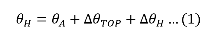
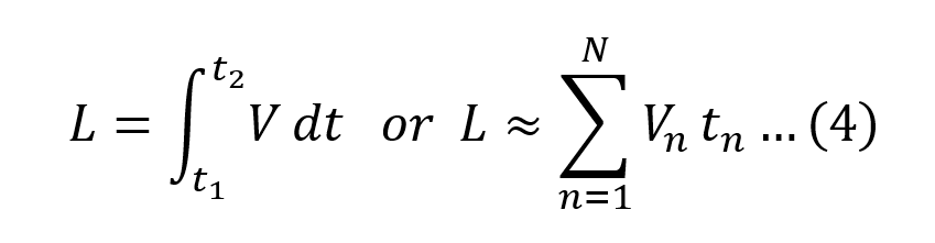
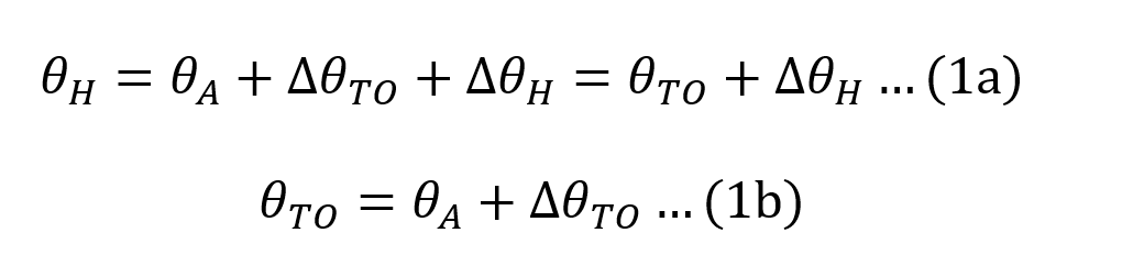
The Transformer Loss of Life (LoL) is based on knowing the HST [3]. It is generally adopted that the HST is given by (1).

Where:

θH is the HST;

θA is the average ambient temperature during the load cycle;

∆θTO is the top oil temperature rise; and

∆θH is hot-spot to top oil temperature rise.

Traditional models [1, 2] estimate the HST based on (1) and require inputs that include: (i) parameters specific to the transformer; and (ii) real-time measurements of ambient temperature, top oil temperature and load current. In recent years transformer manufacturers have included fibre optic sensors (FOS) distributed throughout the windings which conveniently provide an accurate HST measurement leading to a better estimate of the LoL. There are still many transformers in the field that do not incorporate FOS and rely on traditional models for maximising their useful lifespan. This work describes two traditional models for estimating the HST in oil immersed transformers; the models are solved for the HST and compared.

HST models

In our applications, the top oil temperature is provided (measured) and therefore analysis is limited to models that consider only the hot-spot to top oil temperature rise.

Model 1: The model referred to in Clause 7 [1] as ‘transient heating equation’ is based on work by Kennelly [4] who showed that the winding temperature rise above room temperature is exponential, and Cooney [5] who proposed that the winding temperature rise above top oil and the top oil temperature rise can be treated separately. The model assumes an average ambient temperature of 30°C and step changes in load.

The transient winding HST rise over top oil temperature is given by (2).
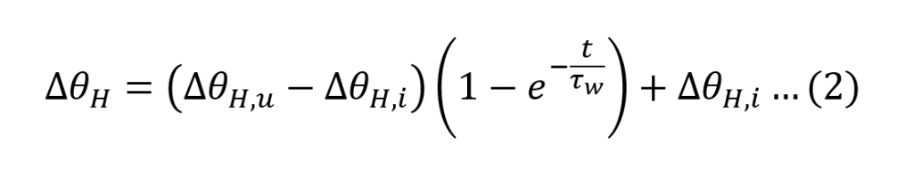
Where:

t is the duration of the load;

∆θH is the hot-spot to top oil temperature rise.

∆θH,u is the ultimate winding hottest-spot rise over top oil temperature for the load;

∆θH,i is the initial winding hottest-spot rise over top oil temperature for t=0; and

τW is the winding time constant at the hot-spot location (4.8 minutes [6]).

The initial and ultimate HST rises over top oil temperature are given by (3).
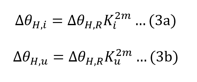
Where:

m is an empirically derived exponent to calculate the variation of ∆θH with changes in load (this varies with the type of cooling and equal to 0.8 for ONAN cooling [1];

Ku is the ratio of ultimate load to rated load;

Ki is the ratio of initial load to rated load; and

∆θH,R is the winding hottest-spot rise over top-oil temperature at rated load (typical values range from 20°C to 35°C [6]).

Model 2: The most recent model [2], is based on work by Swift [7] who proposed a thermal model of a power transformer based on heat transfer theory with an equivalent electrical circuit for determining the HST, shown in Figure 1.

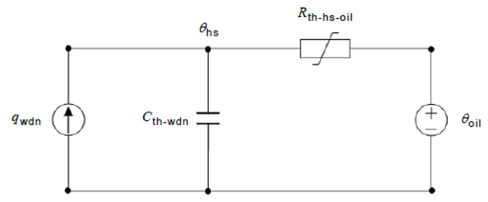
Figure 1: Thermal model of winding-to-oil heat transfer

The current source qwdn is the heat generated by the winding losses, Cth-wdn is the thermal capacitance of the winding, Rth-hs-oil is the non-linear winding to oil thermal resistance, and θhs is the HST. Swift’s model is further extended by considering the hot-spot rise dynamic as differences between the fundamental hot-spot rise and the effect of the varying oil flow that influences the HST given by (4).

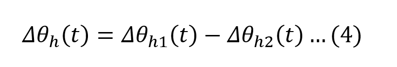
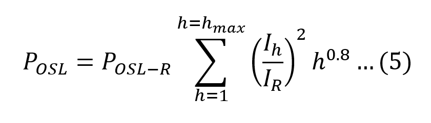
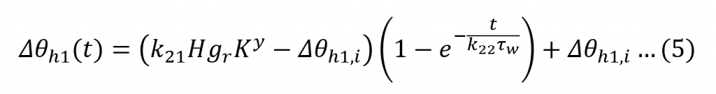
∆θh1 represents the change in the fundamental hot-spot rise given by (5).

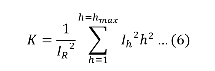
∆θh2 epresents the varying rate of oil flow past the hot-spot, a phenomenon which changes much more slowly and given by (6).

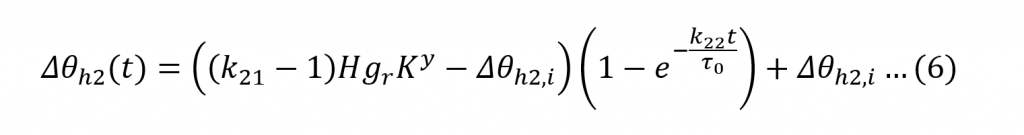
The combined effect of (5) and (6) account for the scenario where a sudden rise in the load current may cause an otherwise unexpectedly high peak in the HST rise, very soon after the sudden load change [2]. Additionally, k21 and k22 are dimensionless parameters and shape (5) and (6) according to Table 1.

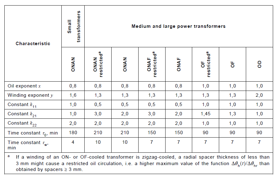
Table 1: Recommended thermal characteristics for exponential equations [2]

Model solutions

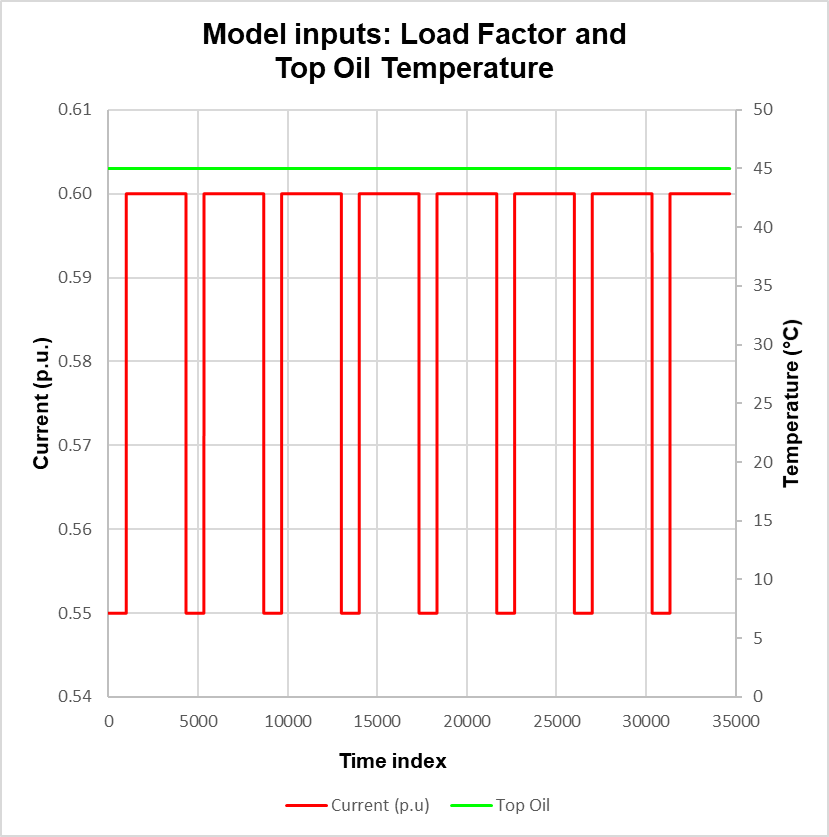
In this section equations are solved numerically for various scenarios. The actual time is equal to the time increment, set to 0.0167 minutes, multiplied by the time index shown in the graphs. Distributions of Load Factor (LF) and top oil temperature, shown in Figures 2 and 4, are created for the purpose of highlighting the characteristics of the models.

Figure 2: Load Factor and top oil temperature profiles
Figure 3: HST model comparison

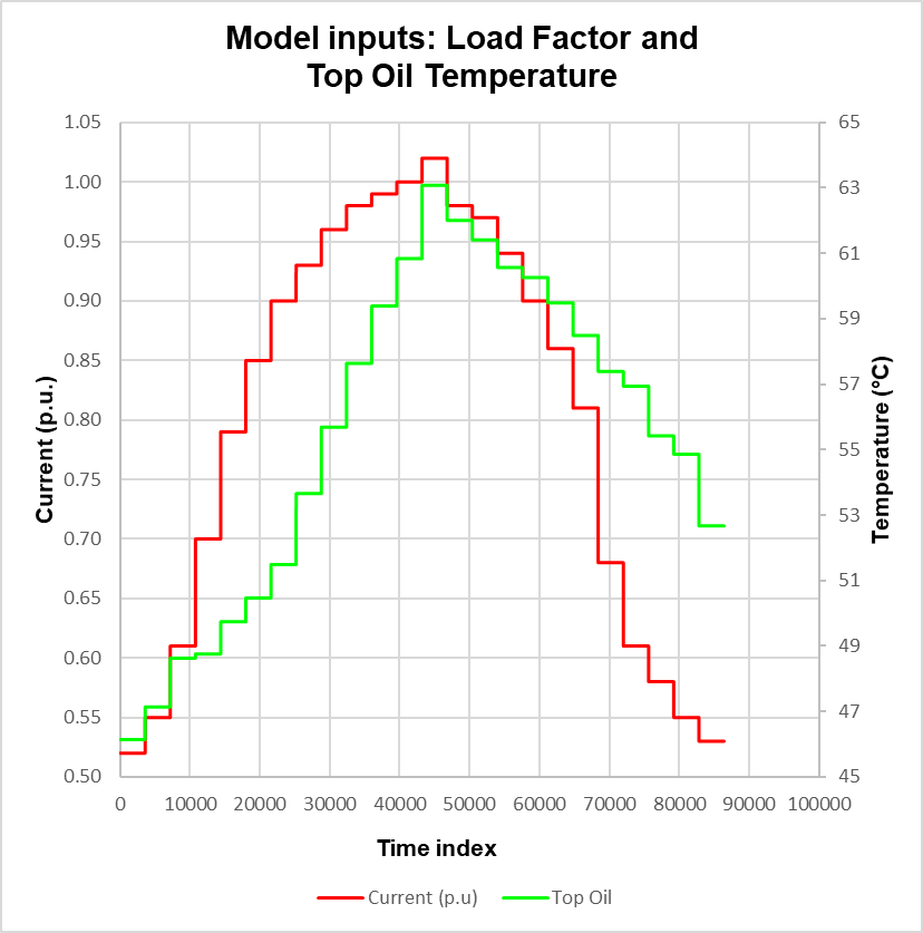
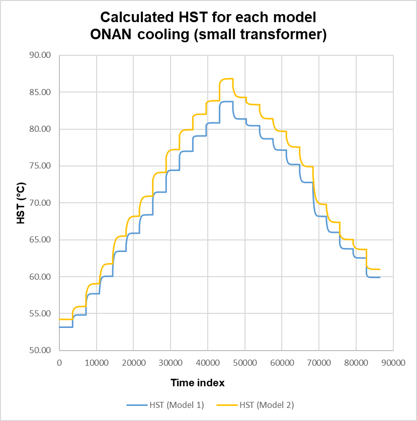
In the case where k21 is set to 1, (6) vanishes because the initial value Δθh2,i is zero leaving only (5). Equations (5) and (2) with (3b) reduce to the same functional form; noting the difference in time constants, τw in (2) and k22τw in (5). Solutions to (1) are shown in Figure 3. As expected, the HST distributions essentially follow the step responses in the top oil temperature profile and also exhibit the exponential growth and decay in accordance with the LF. The maximum variation, Model 2 minus Model 1, is ~3.2°C and occurs at the start of the peak of the LF profile. This is due to the differences in parameters, otherwise both models yield no variation.

Figure 4: Load Factor and top oil temperature profiles
Figure 5: HST Model 2

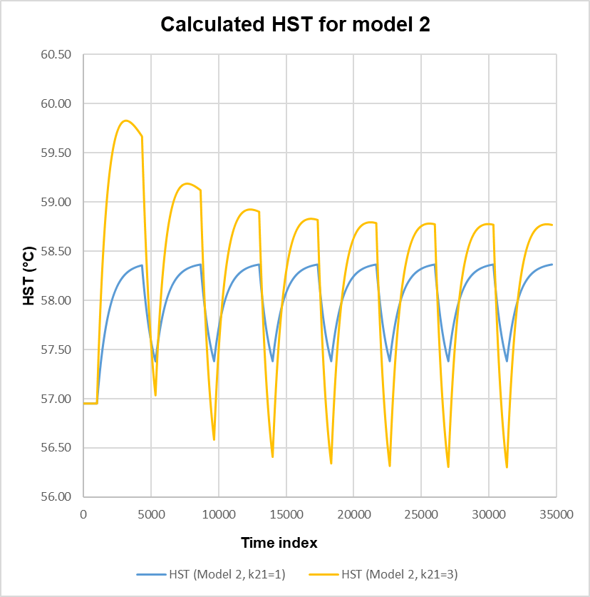
The thermal effect of the oil on the winding HST rise in Model 2 is further investigated by setting k21 to 1 and 3 and by applying the distributions shown in Figure 4. When k21 is set to 1, the effect of oil is not included and the transient behaviour is solely due to the winding constant. Setting k21 to 3 ensures the contribution of the oil time constant in (6) and with (4) now resulting in a subtraction of two first order step responses. The effect is shown in Figure 5, with the response initially exhibiting significant overshoot in the first three excursions and eventually settles to a final value. The effect is due to the inertia of the oil, and is more prevalent in ONANa and ONAFa transformers where oil circulation is restricted, refer to Table 1. The slow decay in the response is due to the oil constant which is ~ 21 times that of the winding constant.

Transformer Monitoring
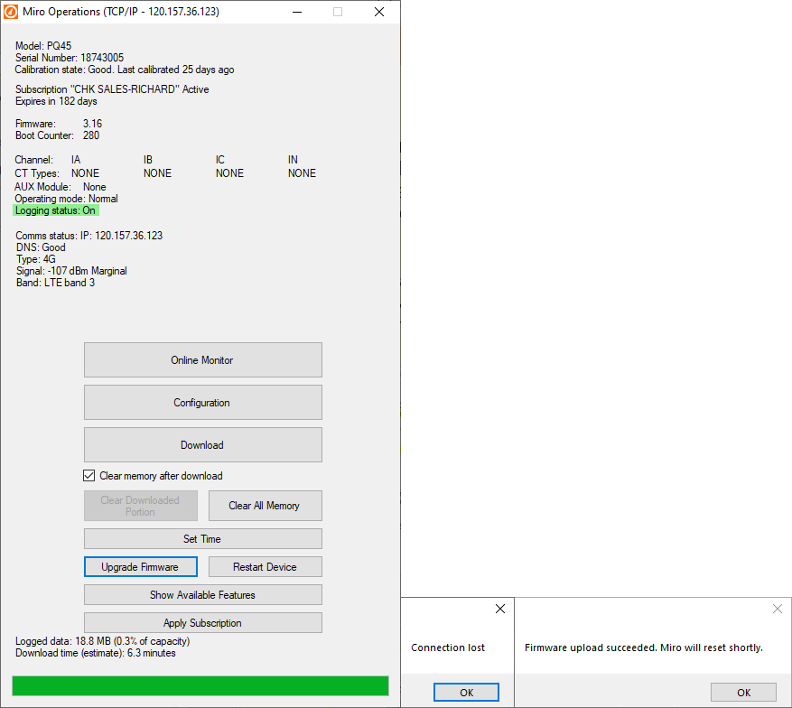
CHK Power Quality Pty Ltd offers the Miro-F TXM Transformer Monitor and Logger (TxM), an instrument purposely suited for comprehensive monitoring of transformer health and can provide LoL calculations based on the IEC and IEEE Standards.

The TxM includes two temperature sensors which can be software configured to measure the top oil and ambient temperatures. Where the transformer is equipped with multiple winding temperature sensors the TxM, together with the Miro Auxiliary I/0 module (Miro Aux), can utilise these inputs in its LoL calculations.

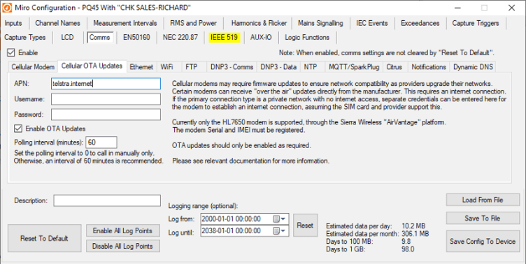
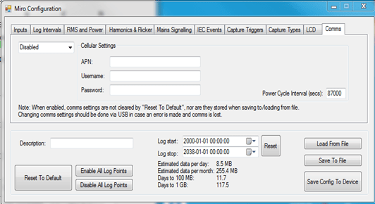
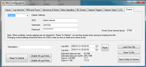
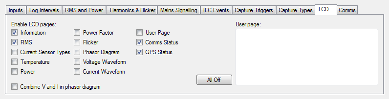
Setting up and configuring the TXM requires the user to populate a template with relevant transformer ratings and other known parameters specific to the transformer. Alternatively, the user can use default values, provided in the TxM, for parameters that are not readily available on the transformer’s name plate.

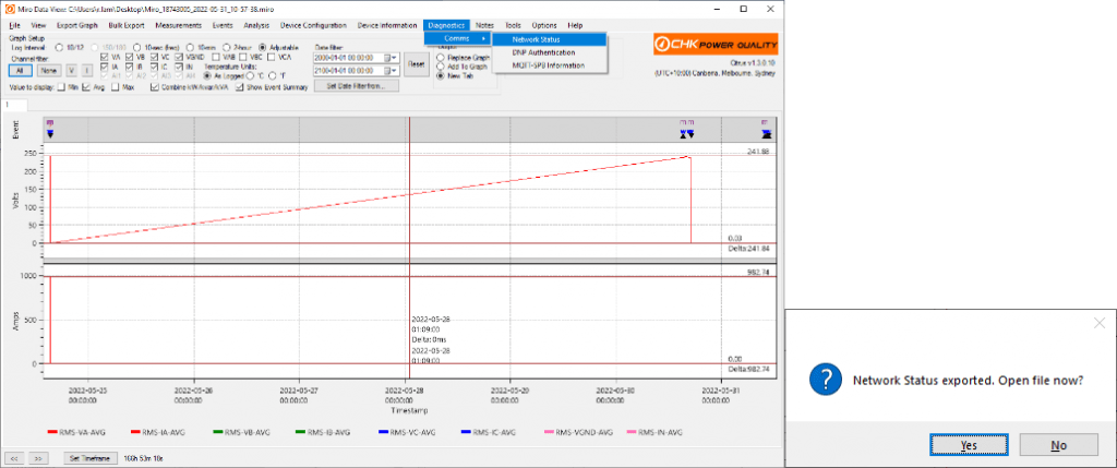
The TxM together with the Miro Aux can expand the monitoring to include geomagnetic DC current; dissolved gases such as oxygen; moisture; on load tap changer (OLTC) operation; bushing leakage current; and fan operation. All these parameters can, not only be displayed alongside critical power quality information but also correlated for in depth analysis.

References

[1] “IEEE Guide for loading mineral-oil-immersed transformers and step-voltage regulators”, IEEE Standard C57.91, 2011.

[2] “IEC Power transformers, Part 7: Loading guide for oil-immersed power transformers”, IEC 60076-7, 2018.

[3] “Introduction to Transformer Loss of Life – based on models from IEC and IEEE loading guides”, Transmission and Distribution, Issue 3, June-July 2021, pp. 38-40.

[4] A. E. Kennelly, “The Thermal Time Constants of Dynamo-Electric Machines”, Winter Midwinter Convention of the A.I.E.E Transactions, New York, USA, Feb. 9-13, 1925, pp. 137-154.

[5] W. H. Cooney, ”Predetermination of Self-Cooled Oil-Immersed Transformer Temperatures Before Conditions are Constant”, A.I.E.E Transactions, vol. 44, pp. 611-618, 1925.

[6] “American National Standard guide for loading mineral-oil-immersed power transformers up to and including 100MVA with 55°C or 65°C winding rise”, ANSI/IEEE Standard C57.92, 1981.

[7] G. W. Swift, T. S. Molinski, and W. Lehn, “A Fundamental Approach to Transformer Thermal Modeling – Part 1: Theory and Equivalent Circuit”, IEEE transactions on power delivery, vol. 16, No. 2, pp. 171–177, April 2001.

Technical note – MIRO Automatic FTP Uploads

This guide introduces how to setup an FTP system with automatic data uploads for the MIRO Power Quality Logger and Analyser.

Introduction

Purpose

The FTP upload option provides automatic data collection without needing an application which periodically polls data to manage it.

This has numerous advantages:

  • Unsolicited reporting instead of polling allows for the device (MIRO) to initiate all connections, removing the need for a static IP for each unit.
  • Compatible with all SIMs – most public internet SIMs provide a private IP address behind a router/firewall (ie. carrier-grade NAT), effectively blocking all incoming connections. Remember that cellular data services are geared up for smartphones and tablets; machine-to-machine services are a niche application.
  • Only the server needs to be static and externally accessible – this is rarely an issue with a wired connection.
  • More secure than a polled solution with a public static IP.
  • Private IP SIMs can still be used, as long as the server is located within the same private network.
  • Many different server options are available across multiple operating systems rather than specifically requiring a Windows PC.
  • Third party FTP hosting solutions can be used
  • Third party services to receive files via FTP and transfer to another service such as Dropbox are available.
Gapless logging

FTP uploads, like CITRUS downloads, will not interrupt measurement or logging. Data is cleared on successful uploads, and only the data that was for example, and then other PCs may access the files directly through a mapped network drive without needing an FTP client.ou will need either a static IP in your office (usually standard with any wired business internet service) or a dynamic DNS service. A static IP is strongly recommended because this is the simplest and most reliable option.

You will need either a static IP in your office (usually standard with any wired business internet service) or a dynamic DNS service. A static IP is strongly recommended because this is the simplest and most reliable option.

Contact your ISP for more information.

An FTP server is included in Windows Server 2008 and later, but it can be difficult to set up. A popular server that works on any version of Windows is FileZilla: https://filezilla-project.org/

Documentation is available here: https://wiki.filezilla-project.org/Documentation

The server should be set up in “passive” mode. This is usually the default.

Port forwarding will need to be set up on your router. The router’s manual should explain how to do this. Both the primary port (21 by default) and the range of passive-mode ports (eg. ports 5000 to 5100) will both need to be forwarded.

Miro Setup

CITRUS v1.0.4 or later is required, and MIRO firmware v1.08 or later. (Updating to the latest versions from our website is always recommended.)

Logging – Data Volume

The volume of the logged data should be considered carefully as cellular data can be quite limited and/or expensive. An estimated data volume per day and month is provided in the configuration form to help manage this, but the actual amount of data could be larger or smaller depending particularly on how many event captures are taken.

The MIRO does not use segmented memory, and so there is no upper limit to how many waveform/RMS captures can be stored, though (as of firmware 1.08) there is a cap of 300 captures per day. This value may be altered or made configurable in future versions.

For long term installations, it is recommended to compare the size of the first few uploaded files against the estimates. If more events than expected were captured or if the file size is otherwise much larger, consider the following: automatic filename to the end. The name will be the serial number followed by a date and time. Example: 15749004_2016-09-18_04-01-04.miro.

It is recommended to use only letters, numbers, underscores (_) and dashes (-) in the filename.

If files from different units should go in different folders, then either set up a separate FTP username for each, and configure a separate folder in the server, or use the same account but specify a path. Folders will need to be created manually; the MIRO will expect the path to exist already.

Make sure to use forward slashes (/), as this is what FTP expects. This differs from the backslash (\) typically used by Windows.

As an example, the server may be configured with a single username tied to the folder “c:\ftproot”. If three units (serial numbers 1111, 1112, 1113) are set up as follows:

  • unit_one/Miro_
  • unit_two/Miro_
  • unit_three/Miro_

Then the resulting upload paths will be:

  • c:\ftproot\unit_one\Miro_1111_2016-09-18_04-00-37.miro
  • c:\ftproot\unit_two\Miro_1112_2016-09-18_04-02-20.miro
  • c:\ftproot\unit_three\Miro_1113_2016-09-18_04-01-12.miro
Initial Upload

On power up or shortly after FTP uploading is enabled, the MIRO will perform an upload to verify that the connection is working. The Comms page on the LCD can be used to verify that the upload worked if access to the server is not immediately available.

Upload Trigger

Two conditions are currently offered.

  • Upload daily or weekly
  • Upload when size reaches 20MB or 100MB

Both options may be selected at the same time.

Daily uploads (as of CITRUS 1.1.6) occur at 18:00 UTC time. This will be 4:00 or 5:00 Sydney time depending on daylight savings. Weekly uploads occur early Monday morning at this time.

Remote management and Time Synchronisation

The following features all require firmware v2.13 or later and Citrus v1.1.6 or later.

Configuration

The settings can be found on the FTP upload page:

Firmware Update

If enabled, the Miro will check for firmware updates after a successful upload. It will check for a firmware file with a name similar to the uploaded data file, based on the configured prefix and serial number. For the previous example “unit one”, where the uploaded file path was:

  • c:\ftproot\unit_one\Miro_1111_2016-09-18_04-00-37.miro

The firmware update filename would be:

  • c:\ftproot\unit_one\Miro_1111.fw

This ensures that only the correct unit is updated.

After downloading and verifying the firmware file, the Miro will delete the file on the server and then reboot to apply the new firmware. As starting up automatically triggers an upload, confirmation is quickly provided that the firmware version was updated.

In short, the update can be performed by taking the latest firmware from our website, uploading it to the FTP server and then moving/renaming it as required, then simply waiting for the upgrade to take place.

Configuration Update

Configuration can be updated in a similar manner. If FTP configuration updates are enabled, the Miro will check after a successful upload for a configuration file with a particular name. Continuing the above example, the file path for “unit one” would be:

  • c:\ftproot\unit_one\Miro_1111.miroremoteconfig

actually uploaded is cleared. Any data logged during the upload is maintained, and will be sent during the next upload.

Files from the same MIRO can be joined in CITRUS to produce graphs of weeks or months of data with no gaps.

Connecting with CITRUS

If a static IP is used, it is still possible to connect directly with CITRUS and download even if FTP uploading is enabled.

Server Setup

Server setups differ depending on whether public (internet) or private SIMs are used and (for the public case) on whether the server should be hosted externally or internally.

Private Network

In this case, the server will need to be located within the private network and directly accessible (by hostname or IP) from the remote units.

The files will then be accessible either by connecting to the server via an FTP client (eg. FileZilla Client) or through a mapped network drive.

Your IT department will need to set this up.

Third-party hosted (recommended)

FTP hosting is widely available with different options for storage, monthly data caps, user accounts etc.

Data can then be downloaded from the server by connecting to the server with any FTP client (such as FileZilla client).

Contact us if you are unsure which provider to use. We can help select a provider/plan and set it up on your behalf.

Self-hosted (advanced)

This option will take longer to set up but will be cheaper and may be easier to use. The FTP server could be configured to place files in a shared folder,

  • Set the adjustable interval to 60 seconds or more, or disable all except IEC 10 minute and 2 hour intervals.
  • Enable only the first 25 or 50 harmonics unless problems at higher harmonics are suspected.
  • Disable sliding reference triggering from current:
  • All channels including current are always captured regardless of the trigger source
  • Large jumps in current usually have a corresponding voltage drop
  • Raise the sliding reference threshold(s).
  • Raise the transient threshold. In some installations, there will be large numbers of relatively minor events such as that shown in figure 1, which may not be of interest.
Figure 1: Minor transient event
  • Disable mains signalling captures and use the maximum-detection only.
Server Details

Regardless of how the server is set up, there are four pieces of information which you need:

  • Server hostname or IP. Examples:
    • ftp.example.org (publicly accessible hostname)
    • 203.0.113.20 (publicly accessible IP)
    • 172.16.100.1 (private IP)
  • Server port, such as 21
  • Username
  • Password

A path and/or prefix is optional. The MIRO will take the value entered in the text box and attach an A random delay up to 5 minutes is added to prevent multiple units all trying to log in to the server at the same moment.

This time was chosen as cellular network load is usually very light at this time. The exact time is arbitrary as the upload process does not leave any gaps in the data.

Example

In this example, the MIRO will connect to a server we have set up in a workstation in our office, and upload files into the folder test­_daily­­_upload daily or earlier if data reaches 20MB:

After running for a few days, these files were available on the server:

Retries

If an upload fails, the Miro will attempt the upload again after a delay. There is a maximum of five retries. The delay starts at one minute and doubles each try (“exponential backoff”). After five failed retries, the upload is cancelled and the Miro returns to waiting for an upload trigger condition.

(If the size trigger is used, then it will re-trigger immediately, as the memory will not have been cleared, and the process will loop until the server issue or communications issue is resolved.)

The Comms page on the LCD indicates if the device is currently waiting to retry or if the process failed.

1 . After downloading and validating this file, the Miro will apply the configuration and then delete it from the server. As the Miro was designed to allow configuration at any time, it will keep operating as usual with no interruption to logging.

The file must be in “remote configuration” format. This format contains all the same information as a normal configuration file, except that it requires the user to explicitly authorise it for automatic remote application.

To produce the file, the user should load the configuration from the most recent upload by opening offline configuration and loading the most recent data file, making any necessary changes, then pressing Save To File. If the remote configuration setting is enabled, Citrus will ask the user if the file should be saved in remote-configuration format.

Save this file with the appropriate name, then upload it to the FTP server. Unlike the firmware upgrade, configuration updates won’t trigger an upload, but this isn’t necessary as the deletion takes place after successfully updating. Therefore, seeing the file be deleted is sufficient to confirm the update.

Time Synchronisation – NTP

While the typical clock drift is only one second per week, regular time synchronisation is recommended. NTP can be used to do this automatically, and like FTP it is triggered from the device side and therefore works with all SIM cards and network setups.

Enable Sync Time under the FTP menu. If a particular NTP server is preferred, or if using a private network with no internet access, enter the hostname or IP in the box provided. Otherwise we recommend the following server: pool.ntp.org. This is a publicly available server pool which will automatically redirect the request to an appropriate nearby server.

If NTP is enabled but no server is provided, the Miro will attempt to use the hostname/IP set as the FTP server for NTP as well.

Time sync is triggered automatically after a successful upload. The device will send three requests, take the median offset to the server (accounting for latency) and adjust the clock.

With daily uploads, this will ensure the clock is always within one second of real time.

Technical note – OTA Upgrade for the HL7650 Modem F/W, Using the AirVantage platform, 29 June 2022, rev 1.00

Telephone: +61 2 8283 6945; Fax: +61 2 8212 8105

Website: www.chkpowerquality.com.au

Over The Air Upgrade – Sierra Wireless HL7650 Modem

Updating the Firmware of the Miro’s Wireless 3G/4G HL7650 Modem Remotely, via the Sierra Wireless AirVantage Platform

This guide illustrates how to update the firmware of the Miro instrument’s Sierra Wireless HL7650 modem remotely via the AirVantage platform, for the Miro instrument to be able to operate over Telstra’s upgraded 4G LTE network. The AirVantage platform is provided by Sierra Wireless, the manufacturer of the modem.

Overview

Requirements

The following are required to carry out and complete the upgrade:

  • Citrus_v1.3.0.10.exe
  • miro_v3.16_May04.fw
  • An operating Miro instrument that can be communicated with and installed with a Sierra Wireless 3G/4G HL7650 modem for 3G/4G remote cellular communications
  • SIM card installed in the Miro instrument that can connect to the ‘telstra.internet’ APN. Contact service provider if unsure or if it is not available on the SIM card
  • Internet access and a PC or laptop
  • Basic working knowledge on installing, accessing, and using the Citrus software.

Setting up the Miro instrument for upgrade

Step 1: Install Citrus version 1.3.0.10 using the Citrus_v1.3.0.10.exe file provided.

Step 2: open the Miro instrument’s operation page using Citrus version 1.3.0.10. The Miro’s operations window will appear as shown in Figure 1.


Step 3:
Click on ‘Upgrade Firmware’ and navigate to the folder containing the miro_v3.16_May04.fw firmware. Select the firmware file and click ‘Open’. This will start the firmware upgrade. Firmware upgrade progress will be indicated by the green progress bar at the bottom of the operations window.

Please note that during any restart process in this instruction, it may take several minutes to restart the Miro instrument along with its communications. Multiple connection attempts may also be needed, especially with the SSH secure connection which can take longer to connect.

Once the upgrade is complete the Miro instrument will reset, causing loss of connection as shown below in Figure 2. Open the Miro operations window and note the firmware listed should be ’3.16’.

Step 4: On the operations window, click on ‘Configuration’ to open the Miro configuration page. Navigate to the ‘Cellular OTA Updates’ tab. Tick ‘Enable OTA updates’ and enter ‘telstra.internet’ in the ‘APN:’ box as shown in Figure 3. Please note that “telstra.internet” is used only by the modem to retrieve firmware from the AirVantage website; the Miro instrument itself is not exposed to the internet. Care should be taken that changes are made only in the ‘Cellular OTA Updates’ tab, to prevent loss of remote cellular communication with the Miro instrument. Following the example shown in Figure 3, set ‘Polling interval (minutes):’ to 60 minutes (recommended polling interval). Once done, click ‘Save Config To Device’ and click ‘OK’ in the ‘Configuration set’ pop up.

Step 5: In the Miro operations window, restart the Miro instrument to apply the configuration changes made in the ‘Cellular OTA Updates’ tab. After restart is complete, navigate to the Miro operations window. Download a Miro datafile of the Miro instrument and open the datafile. Click on the ‘Diagnostics’ tab and from the drop-down menu click ‘Comms’ then ‘Network Status’. Choose where to save the Network Status file and then click ‘Yes’ on the ‘Network Status exported. Open file now?’ popup to open the Network Status file as shown in Figure 4.

From the Network Status log, scroll down to the bottom where the latest network status is and note both the IMEI and serial number of the HL7650 modem. As shown below in the Figure 5 example, the IMEI number is listed after the word ‘IMEI:’ i.e., ‘354940080029209’ (underlined in red). The serial number is the number listed after the word ‘+KGSN:’ i.e., ‘TD724385541410’ (underlined in blue). The current firmware version of the modem is also listed i.e., ‘SWIMCB71XX-TIM3.23.01.173400.201708251955.01’ (underlined in green). Note down these values as they will be required later when registering the modem on the AirVantage platform. Repeat Steps 2 to 5 for each Miro Instrument.

Website: www.chkpowerquality.com.au

Creating an AirVantage account

Step 6: Using your internet browser, open the link https://eu.airvantage.net/accounts/signup?type=UFOTA. At the bottom of the page click on ‘SIGN UP’. A new page will then open, enter your details as required to create a user account as seen in Figure 6. Once done, click on ‘SIGN UP’. An activation email will be sent to your email address upon successful sign up as seen in Figure 7. Click ‘SIGN UP ACCOUNT’ to activate account.

Step 7: Log into the newly created account using the following link: https://eu.airvantage.net/start. Upon successful login, the following account page is shown as seen in Figure 8. From the example in Figure 8, we can see that there is a total of two modem units registered on AirVantage with this account. Click on ‘Register new Systems’ (boxed in green in Figure 8).

Step 8: On the registration page under the ‘Register AirPrime HL Series’ box, register the HL7650 modem in AirVantage by choosing the ‘Type’ as ‘HL7650 (GENERIC)’ and inputting the ‘Serial Number’ and ‘IMEI’ that was noted in Step 5 into the corresponding fields. For the ‘Name’, this will be the name of the modem and is up to the user on what name is given. In this example, the modem was given the name ‘demonstration modem’ as seen in Figure 9. Select ‘Pre-configure system’ and then click ‘Register’

Note that multiple HL7650 modems can registered at once by clicking on ‘import a list’ and uploading a CSV file in the required format. For more details see: https://doc.airvantage.net/fota/reference/register/howtos/registerListOfSystems/.

Step 9: A ‘Pre-configure System(s)’ popup will appear as seen in Figure 10. Click on the bins on the right-hand side of the ‘Basic Workflow’ and ‘Send Wakeup’ boxes (boxed in red in Figure 10) to remove the boxes from the workflow.


Under ‘Individual actions’ on the left-hand side of the ‘Pre-configure System(s)’ popup, drag (press and hold left mouse button) the ‘Install Firmware’ (boxed in green in Figure 10) to the right side of the popup and release. This will now bring up an ‘Install Firmware’ box as seen in Figure 11.

In the ‘Install Firmware’ box, from the dropdown menu, select firmware version ‘HL7650 (Generic) (SWIMCB71XX-TIM3.26.00.A01.173700.201804050215.01)’. Note the ‘A01’ which indicates the latest version of the firmware as of March 2022. Once done, click on ‘Pre-configure’. This will close the popup.

Step 10: Upon successful registration of the modem, the modem will appear in the ‘Registered Systems’ box underneath the ‘Register AirPrime HL Series’ box as seen below in Figure 12. If it doesn’t appear, the ‘Registered Systems’ box can be manually refreshed by pressing the refresh button seen in Figure 12 (boxed in red) and the modem should appear in the list. Note that the refresh icon is normally not visible until the mouse cursor is hovering over the area as indicated in Figure 12.

Click on the purple cloud icon (boxed in green in Figure 12) which says ‘See the System details in the Upgrade activity’ when the cursor is put over it. This will take you to the upgrade page for that modem.

Step 11: With the modem set for pre configuration, AirVantage will automatically attempt to synchronise to the modem after registration as seen in the ‘Systems Operations’ box in Figure 13.

For successful synchronising with the modem and later the firmware upgrade, the modem needs to poll the AirVantage platform. With the polling interval set to 60 minutes, wait for the modem to poll AirVantage and wait for successful synchronisation as seen in Figure 14. The refresh icon may need to be clicked (boxed in red in Figure 14) to see the successful synchronisation.

Step 12: After AirVantage has successfully synchronised with the modem, the modem will automatically attempt to install the firmware for the modem and the ‘Install application’ task will appear in the ‘System Operations’ box as seen in the ‘Upgrade’ page of the modem in Figure 15 (refresh icon may need to be

Step 13: During modem firmware upgrade, 3G/4G connection will be reset and so connection of the Miro instrument to Citrus will be lost. Once the upgrade has been completed, the ‘Install application’ progress bar in the ‘Upgrade’ page will be completely green and the ‘Firmware’ version will be displayed in ‘System Info’ as shown in Figure 16 (boxed in red). The refresh icon on the ‘Upgrade’ page (boxed in green in Figure 16) may be required to be clicked more than once during and after upgrade to see the updated statuses on the ‘Upgrade’ page.

Alternatively, to check that the modem has the latest version of the firmware installed, check the network status log of the Miro instrument and note the firmware number now listed as ‘SWIMCB71XX-TIM3.26.00.A01.173700.201804050215.01’ (underlined in red in Figure 17).

Step 14: With the modem firmware update done, the OTA updates for the Miro instrument needs to be turned off. To do this, untick the ‘Enable’ box on the ‘Cellular OTA Updates’ page on Citrus (see Figure 9). Repeat Steps 8 to 14 for each Miro Instrument as necessary.

Step 15: Once upgrade of all HL7650 modem firmware is successful, the Citrus software needs to be reverted back to the latest released version. This can be found on CHKPQ’s website via the link: https://www.chkpowerquality.com.au/downloads/

and as seen in Figure 18. The link to download the Citrus software on this page is underlined in red.

Install the Citrus software version available for download from the CHKPQ website to the same folder where Citrus version 1.3.0.10 is located. This will overwrite Citrus version 1.3.0.10. The upgrade process is now complete.

Technical note – OTA Upgrade for the HL7650 Modem F/W, Using the AirVantage platform, 29 June 2022, rev 1.00

Telephone: +61 2 8283 6945; Fax: +61 2 8212 8105

Website: www.chkpowerquality.com.au

An Introduction to Transformer Harmonic Current Derating Metrics

Abstract

Transformer harmonic current derating metrics; Harmonic Loss Factor, K-Factor, and Factor K are introduced, and used to calculate derating factors for dry and oil-filled type transformers.

Introduction

The introduction of Switched Mode Power Supplies (SMPS) in office equipment and LED lighting, Variable Frequency/Speed Drives (VF/SDs) to operate induction motors, and inverters that change DC, from photovoltaic cells, to Mains Frequency AC to drive Mains Frequency equipment or even feed upstream into the power grid are just some examples of how electronics are helping to increase efficiency in power usage. One drawback is their non-linear nature, which can yield significant voltage and current harmonic content both at the input and output, if not appropriately filtered. Harmonics on supply lines feed upstream into transformers, causing higher than expected heating and ageing. Excessive heating could lead to catastrophic outcomes (Picture 1). This work introduces three metrics; Harmonic Loss Factor, K Factor, and Factor K; developed to assess the impact of current harmonic heating of transformers.

Picture 1: Transformer on Fire

Transformer losses

The IEEE Standard C57.110-1986 [1] is developed to limit transformer temperature rise due to non-sinusoidal load currents [2]; it describes the load losses and a method to calculate load reduction required, so as to not exceed rated losses given the harmonic spectra of the load current.

Total transformer loss PT (1) is the sum of no-load loss (excitation loss) PNL and load loss (impedance loss) PLL.

It is assumed in the proceeding work that the voltage harmonic distortion does not significantly increase the excitation loss, leaving the load loss the dominating source of loss at rated load. The load loss consists of copper loss, P (also referred to as I2R) and stray losses PSL. Stray loss is due to stray electromagnetic flux in the winding, core, core clamps, magnetic shields, enclosure, or tank walls [1]. The stray losses can be decomposed into eddy current losses in the winding PEC and other stray losses POSL (2).

The copper loss is given by (3) and where the RMS current is decomposed into its harmonic content.

Winding eddy current loss in the power frequency spectrum is proportional to the square of both the load current magnitude and its frequency; and can cause excessive heating and abnormal temperature rise in the presence of non-sinusoidal load current.

It is found that other stray loss increases with the square of the current magnitude and by a harmonic exponent factor no greater than 0.8 [3].

PEC-R and POSL-R are losses under rated conditions, and where IR and is the rated current.

K-Factor

Underwriters Laboratories (UL) developed a metric called the K-factor [4], (6), a rating optionally applied to a dry-type transformer indicating its suitability for use with loads that draw non-sinusoidal currents and weights the harmonic currents according to their effect on transformer heating. The K-factor requires the rated current of the transformer.

The K-factor is used to specify a class of transformers capable of serving non-sinusoidal loads. K-factor rating of a transformer e.g. (4, 9, 13, 20, 30, 40 or 50) is an indication of the amount of harmonic current the transformer is capable of handling without overheating. The measured K-factor of the load must be below the K-factor rating of the transformer.

When comparing (4) and (6), the K-factor provides a measure of the ratio of the winding eddy current loss PEC to the eddy current loss under rated conditions PEC-R and therefore, a K-factor greater than unity indicates heating exceeding the rated operating conditions of the transformer. A standard transformer that is designed for linear loads is said to have a K-factor of unity.

Harmonic Loss Factor

Harmonic loss factor FHL is defined in (7) as the ratio of the total winding eddy current losses due to the harmonics, PEC, to the winding eddy current losses at operating current and power frequency, as if no harmonic currents existed, PEC-O [1].

Similarly, the harmonic loss factor for other stray loss FHL-STR is calculated using (8) but not critical in estimating the derating in dry-type transformers [3].

Note: is other stray losses at operating current and power frequency, as if no harmonic currents existed.

The K-factor and harmonic loss factor are related using (9).

From (9), the K-factor and FHL are equal only when the RMS current value is equal to the rated current of the transformer. Under normal operating conditions the RMS current value should be less than the rated current and so the K-factor is less than FHL .

Derating

The maximum amount of harmonic load current that a standard transformer can deliver without exceeding rated operating conditions is given by (10) [5]. max (pu) is also used as a derating factor.

For dry-type transformers POSL-R (pu) is zero and (10) reduces to (11).

From (11) no derating is required when FHL is unity. Equation (11), rewritten in terms of K-factor will yield the same value of derating. The UL standard [4] prescribes another method for derating dry-type transformers using K-factor.

Factor K

Another method used to derate a standard oil-filled transformer to harmonic load is referred to as Factor K [6] and given in (12).

e is the eddy current loss due to sinusoidal current at the fundamental frequency, divided by the loss due to DC current equal to the RMS current of the sinusoidal current value, both at reference temperature. The exponent q is dependent on the type of windings and on the frequency. As a guide, q is set to 1.7 for transformers with round or rectangular wire in both low and high voltage windings and to 1.5 for transformers having low voltage foil windings. The derating factor is given by 1/FK.

Worked example

A VSD is connected to a transformer rated at 200A. The input current spectrum to the VSD resembles that of a six-pulse rectifier and normalised to 104.1A RMS. The rated eddy current loss PEC-R , e and q are set to 10%, 0.1 and 1.7 respectively. The transformer harmonic derating metrics are calculated using equations (6), (7), (8) and (12). Equations (11) and (12) are used to calculate the derating of dry-type and oil-filled type transformers respectively.

Figure 1: Transformer harmonic derating metrics

The maximum harmonic number is limited to 25 as provided in the IEEE Standard C57.110-1998 [3]. It is noteworthy that the skin effect becomes more pronounced with frequency and eddy-current loss is smaller than predicted; values are conservative in particular above the 19th harmonic [3].

In Figure 1 at each harmonic number, the harmonic derating metrics are calculated considering contributions of harmonics up to and including the harmonic number; and as expected the metrics increase in value with increasing harmonic number. The values at the 25th harmonic for FHL , K-factor, FHL-STR and Factor K are 8.35, 2.26, 1.34, and 1.15 respectively.

Figure 2: Derating – dry and oil type transformers

In Figure 2 the derating factors for dry-type and oil-filled type transformers are 77.4% and 87.2% respectively with equivalent operating currents of 155A and 174A.

Please contact CHK Power Quality for a free and no obligation demonstration or trial.

Phone: +61 2 8283 6945
Email: sales@chkpowerquality.com.au

References

[1] IEEE C57.110-1986, “IEEE Recommended Practice for Establishing Transformer Capability When Supplying Nonsinusoidal Load Currents”.

[2] M.A.S. Masoum, P.S. Moses, A.S. Masoum, “Derating of Asymmetric Three-Phase Transformers Serving Unbalanced Nonlinear Loads”, IEEE Transactions on Power Delivery, Vol. 23, No. 4, October 2008, pp. 2033-2041.

[3] IEEE C57.110-1998, “IEEE Recommended Practice for Establishing Transformer Capability When Supplying Nonsinusoidal Load Currents”.

[4] UL-1561-1994, “Dry-Type General Purpose and Power Transformers”.

[5] S.B. Sadati, A. Tahani, M. Jafari, M. Dargahi, “Derating of Transformers under non-sinusoidal Loads”, International Conference on Optimization of Electrical and Electronic Equipment, Brasov, Romania, pp. 263-268, 2008.

[6] EN50464-3: 2007, “Three-phase oil-immersed distribution transformers 50Hz, from 50kVA to 2500kVA with highest voltage for equipment not exceeding 36kV – Part 3: Determination of the power rating of a transformer loaded with non-sinusoidal currents”, April 2007.

Configuring the MIRO for cellular communications

This guide illustrates how to configure a MIRO Power Quality Logger and Analyser for cellular communications.

Installing the SIM

Step 1 : Unplug the MIRO from the all power sources (including the communications cable). The MIRO has a backup battery and will power down in five minutes if it was powered with a single phase or three phase voltage lead.

Step 2 : Loosen the screws on the top cover and remove carefully. There are no attachments between the top cover and the enclosure.

Figure 1: Miro with cover removed

Step 3 : If required, the unit can be powered down immediately by pressing the reset button indicated by the arrow in figure 2.

Figure 2: Arrow showing reset button

Step 4 : Insert the micro SIM, ensuring the card is oriented correctly and the metal contact on the SIM is face down.

Figure 3: Showing orientation of SIM

The card must be pushed in fully and can be done using your fingers.

Figure 4: Showing inserted SIM

Once inserted, the SIM can be removed using a pen.  

Place the tip of the pen to the edge of the SIM as shown in figure 5.

Figure 5: Pen placed at the edge of the SIM
Figure 6: Pen used to nudge the SIM out of the holder

Step 5 : Replace the top cover carefully, and tighten the screws, taking care NOT to overtighten to the point where the top cover edges start to bow. Tightness is sufficient when the edges of the top cover and enclosure meet.

Configuring the instrument

Step 6 : Connect the instrument to a lap top or PC, using the supplied USB communication cable. Double click on the Citrus icon on the desktop to launch the Citrus Software application. The form shown in figure 7 appears.

Figure 7: Citrus – instrument selection

Step 7 : Click on the ‘Miro’ button shown in figure 7. A form providing management options appears as shown in figure 8

Figure 8: Citrus – Management options

Step 8 : Click the ‘Connect USB’ button and then the ‘Configuration’ button. A configuration form appears. Select the ‘Comms’ tab.

Figure 9: Comms configuration page

Step 9 : Enter the APN, Username, Password, and select ‘Cellular’ in the top left hand corner drop down box as shown in figure 10.

Figure 10: Comms configuration page – filled

Step 10 : Click on the ‘Save Config to Device’ button.

The instrument has now been updated with the new configuration and is now enabled for Cellular communications.

Step 11 : If you wish, click on the LCD tab and tick the ‘Comms Status’ checkbox as shown in figure 11.

Figure 11: LCD configuration page

Step 12 : Then again click on the ‘Save Config to Device’ button.

The MIRO when next powered up will display on the graphical LCD the comms status and other information as selected in the LCD tab in the configuration menu. An example is shown in figure 12.

Figure 12: Graphical LCD

Note: SIM must have a fixed IP address.

Introduction to Transformer Loss of Life – based on models from IEC and IEEE loading guides

Abstract

This work introduces the concepts of Hot-Spot Temperature (HST) and transformer ageing due to temperature and how the HST affects transformer life expectancy. The relative ageing rate of two models are compared for various scenarios and the Transformer Loss of Life (LoL) is estimated for two HST profiles.

Introduction

LoL is the term used to express how much life a transformer has lost since being commissioned. One factor which accelerates ageing of the transformer and increases its LoL is the HST. The IEEE [1] and the IEC [2] loading guides provide models for estimating the LoL utilising the HST.

Determination of the HST

Figure 1 shows a simplified model of the temperature distribution within an oil-immersed power transformer, with the following assumptions [3]:

  • the oil temperature inside the windings increases linearly from bottom to top regardless of the cooling mode;
  • the temperature rise on the conductor at any position up the winding increases linearly and parallel to the oil temperature rise, with a constant temperature difference of ‘g’; and
  • the HST rise is higher than that of the conductor at the top of the winding to allow for increases in stray losses and is accounted for by multiplying ‘g’ by the hot-spot factor ‘H’; which may vary from 1.1 to 1.5, (1.0 to 2.1 [2]) depending on transformer size, short-circuit impedance and winding design.
Figure 1: Thermal diagram of a transformer [4]

The HST is the sum of the ambient temperature θA, top oil temperature rise ∆θTOP , and the hot-spot to top oil temperature rise ∆θH.

Ageing models

Ageing of the transformer paper insulation is dependent on temperature and contents of moisture, oxygen, and acid. Models presented here focus only on temperature and in particular the HST since deterioration is normally highest at the top of the winding.

The IEC standard refers to the relative ageing rate, V whereas the IEEE standard refers to the ageing acceleration factor, FAA . Both are utilised in the same way to calculate lifetime consumption. In this work we adopt V .

Model A: Non-thermally upgraded paper. The relative (thermal) ageing rate, V , is referenced to unity for a HST of 98°C [θHref], at an ambient of 20°C where the HST rise over ambient is 78°C and operating in the range of 80°C to 140°C.

V doubles for every 6°C rise in HST.

Model B: Thermally upgraded paper. V is referenced to unity for a HST of 110°C [θHref], at an ambient of 30°C where the HST rise over ambient is 80°C. 15000 is an empirical constant provided in Annex I [1]. Equation (3) may also be used to model non-thermally upgraded insulation, with V referenced to unity in the case where the average winding temperature rise is 55°C and at a HST of 95°C, with a HST rise over ambient of 65°C.

Equations (2) and (3) are based on the Montsinger [5] and Dakin [6] life expectancy models, a simplification of the Arrhenius relation equation given in A.1 [2].

Figure 2 (left) compares the performance of hot-spot on paper types and shows that the use of thermally upgraded paper can decrease ageing by a factor of as little as 3.4 and at most by 7.4.

Figure 2 (right) compares the models for non-thermally upgraded paper insulation. The results for both models are plotted for the hot-spot range 80°C to 140°C and for the restricted (rest.) range of 80°C to 124°C so as to better highlight the differences. The two models are monotonically increasing, initially with Model B yielding higher values of V, and intersect at a HST of approximately 123°C, after which they commence to diverge and Model A yields higher values of V. The value of V below͢͢ 80°C is negligible for both curves.

Figure 2: Transformer ageing models. Left: Comparing insulation paper types. Right: Comparing models for non-thermally upgraded paper.

Lifetime consumption (loss of life)

Under constant conditions the relative lifetime consumption L can be calculated by the product of V and time elapsed, t2-t1. In practice the load and transformer temperatures change over time, and in which case L is given by (4) [2].

Worked Example: Lifetime consumption estimation for non-thermally upgraded paper.

Consider the HST profile of a transformer over a 24-hour period as provided by the first three columns in Table 1. Assume that the temperature transition times are negligible. Inserting the HST into equations (2) and (3) yields V for those periods (given in columns 4 and 5). The lifetime consumption for each time period is calculated by multiplying V with the time interval and given in columns 6 and 7.

Table 1: Worked example – lifetime consumption estimation

Summing the lifetime consumptions over the 24-hour period shows the transformer actually aged 61.159 hours (Model A) [0.034%] or 74.636 hours [0.041%] (Model B), of its total life span. The percentages are based on a transformer lifespan of 180,000 hours or 20.55 years and assumes the transformer running constantly at the rated HST. This means that if a transformer was subjected to the same daily load profile as in Table 1, its lifespan would be reduced to 70636 hours [8.06 years] (Model A) or 57881 hours [6.61 years] (Model B).

Figure 3 (left) represents the values in Table 1. Figure 3 (right) represents the values in Table 1 but where the HST for the last six hours is changed to 128°C. The profiles are purposely changed to highlight a scenario where Model A can yield a higher LoL if the HST is beyond 123°C.

Figure 3: Transformer ageing for non-thermally upgraded paper and for two hot-spot profiles. Left: HST=110°C for last six hours. Right: HST=128°C for last six hours.

Transformer monitoring

CHK Power Quality Pty Ltd offers the Miro-F TxM Transformer Monitor and Logger (TxM), an instrument purposely suited for comprehensive monitoring of transformer health and can provide LoL calculations based on the IEC and IEEE Standards.

The TxM includes two temperature sensors which can be software configured to measure the top oil and ambient temperatures. Where the transformer is equipped with multiple winding temperature sensors the TxM, together with the Miro Auxiliary I/O module (Miro Aux), can utilise these inputs in its LoL calculations.

Setting up and configuring the TxM requires the user to populate a template with relevant transformer ratings and other known parameters specific to the transformer. Alternatively, the user can use default values, provided in the TxM, for parameters that are not readily available on the transformer’s name plate.

The TxM together with the Miro Aux can expand the monitoring to include: geomagnetic DC current; dissolved gases such as oxygen; moisture; on load tap changer (OLTC) operation; bushing leakage current; and fan operation. All these parameters can, not only be displayed alongside critical power quality information, but also correlated for in depth analysis.

Please contact us for a free and no obligation demonstration or trial.

Phone: +61 2 8283 6945
Email: sales@chkpowerquality.com.au

References

[1] “IEEE Guide for loading mineral-oil-immersed transformers and step-voltage regulators”, IEEE Standard C57.91, 2011.

[2] “IEC Power transformers, Part 7: Loading guide for oil-immersed power transformers”, IEC 60076-7, 2018.

[3] “Loading guide for oil-immersed power transformers”, IEC 60354 second edition, 1991-09.

[4] M. Srinivasan, A. Krishnan, “Prediction of Transformer Insulation Life with an Effect of Environmental Variables”, International Journal of Computer Applications, Vol. 55-No.5, pp 43-48, October 2012.

[5] V. M. Montsinger, “Loading Transformers by Temperature”, Winter Convention of the A.I.E.E, New York, USA, Jan. 27-31, 1930, p. 783.

[6] T. W. Dakin: “Electrical Insulation Deterioration Treated as a Chemical Rate Phenomenon”, AIEE Trans., Vol. 67, pp. 113-122, 1948.

Citrus Release Note

Citrus v.1.4.0.8 (Updated 2024-03-26)

  • Enhanced Multi-parameter capture measurement.
  • Support for Point Condition Monitor (Electric DC)
  • Improved Configuration menu: feature restrictions for LCD pages (phasor diagram, power)
  • Improved Online monitor: derived phase to phase channels on live RMS plot are shown only when applicable.
  • Mirrin:
    • max value and time when max value occur added to status window
    • Daily min/max tables added
    • Support ‘log maximum demand’
    • Support Degrees Celsius and Degrees Fahrenheit temperature units
    • Support channel colours for plots, similar to the Miro power quality analyser
  • Miro secure connection: Feature added where connection retries as the first secure connection after boot is identified to take additional time
  • Enhanced phasor diagram
  • Enhanced power quadrant
  • Updated DNP3 points list to include fundamental powers (active, reactive, apparent, total) points
  • Support ‘Restore From File’ option to re-load older config from the same Miro unit, including comms passwords
  • Support temperature to Miro daily min/max tables
  • Display Miro uptime on status form
  • Yellow highlight for long and 10 second waveform capture
  • Display warning popup message when long or 10 second waveform capture is selected initially
  • Support faster polling of Miro Operation window (e.g. uptime, connected CTs) when on faster connections (e.g. USB)
  • Relocate distortion factor to Miro measurements menu
  • Support Miro model identification for Miro ECO configurable version
  • Miro online monitor: indicate on quadrant power table that it is fundamental power and displacement power factor
  • Support for Miro PQ21
  • Online monitor: tool-tip for negative and zero unbalance
  • Mirrin: disable file-locking on reading files (i.e., data files, firmware file) so they work as intended when located on network drives with limited permissions
  • Export graph as table: data with timestamps that differ by an amount less than a rounding error (e.g. 0.0001 seconds) will now always appear on the same row. Previously they would be on separate rows (with identical rounded timestamps) if the timestamps differed by a smaller amount (e.g. 0.00001 seconds).
    • Note: this would usually only occur when plotting data from two different GPS-sync’d units on the same chart.

Citrus v1.3.0.22 (Updated 2023-03-15)

  • Graphing of transformer loss of life parameters
  • Transformer loss of life calculations can be based on either IEC or IEEE versions
  • Transformer loss of life parameters available in DNP3 configuration form
  • Transformer loss of life analysis tool, including features to analyse different scenarios
  • Bulk export of Transformer loss of life data
  • Support changing temperature unit from Celsius to Fahrenheit or vice versa
    • In the Miro configuration tab
    • Default setting is based on PC region setting but can be changed as necessary
    • Graphing will switch to a new axis if temperature unit were changed during logging
    • CSV export will use setting (Celsius or Fahrenheit) at time of download
    • Online monitor window will have to be closed and reopened if units are changed while online monitor window is open
  • Online monitor now shows an events tab if any event type is available rather than just RMS/waveform capture
  • Show configured temperature unit in DNP point setup
  • Configuration tabs and online monitor now include harmonic derating factors K-factor, Factor-K and Harmonic Loss Factor
  • Analysis of K-factor, Factor-K and Harmonic Loss Factor
  • Factor-K and Harmonic Loss Factor transformer derating
  • Invert current channel tool, post logging
  • Support ‘AirVantage’ OTA updates for HL7650 modem
  • Fundamental frequency now available on online monitor (harmonics)
  • Fundamental frequency now available in harmonic average chart
  • THD/TIHD/K-factor selectable for LCD pages
  • Harmonic derating values analysis for different scenarios
  • Interharmonic average chart now available
  • Improved USB performance
  • Improved data usage estimate
  • NTP interval default setting changed from “on FTP upload” to “daily”
  • Positive/Negative/Zero sequence components available on data view and online monitor. (Requires firmware 3.17)
  • Option to include units in CSV column headers. This is on by default.
  • Auto scroll bar available for EN50160 report generation form
  • Easily selectable events in bar on Miro data view to much more closely match the event letter, reducing overlap
  • Use standard colours for online monitor AUX/temperature plot to match data view
  • Feature to lock the menu bar during the initial graph in Data View tab.
  • Configuration menu. User is warned that ‘Enable-all-points’ doesn’t enable certain points, where applicable
  • User is warned when fundamental mag/phase is not going to be logged

Citrus v1.2.9.1 (Updated 2021-06-21)
v1.2.9.1 Citrus Release Notes

  • Users can now change the font of the title in the event view form.
  • Customised graph set up for each view tab.
  • Hassle free connection to WIFI via button in Miro main menu.
  • Option to change cursor style.
  • Feature that loads graph setup from view when switching tab.
  • Automatic generation of IEEE519 power quality reports.
  • Easy to read ‘Data Range in File’ information.
  • Easy selection of ‘Date Filter’ using drop down menu.
  • ‘Records Excluded’ count now noted in voltage percentiles for more clarity.
  • Feature to ‘save all views’ and ‘load all views’.

Miro Firmware Release Notes

Miro Firmware v3.18 (Updated 2024-03-26)

  • Updated phasor and quadrant power LCD pages
  • Serria Wireless RC7620 modem support
  • Additional DNP3 fundamental power parameters
  • Additional MQTT fundamental power parameters
  • Adjustment of LCD serial number position to avoid clashing with the signal bar
  • Adjust ‘GPS’, ‘WiFi’ (low-speed), ‘TCP’, ‘SSH’ and ‘AUX’ text position on LCD to reduce overlap
  • Support 60 Hz setting for Miro ECOs
  • Configurable-threshold ECO block and bar models
  • ‘high v unbalance’ warning for Delta (was Star only)
  • Amended quadrant power text: PF to DPF
  • CT Types turn dark green on the “current sensor types” LCD page when locked
  • Enhanced sensitivity of “sliding reference minimum”
  • Enhancement of how the sliding reference minimum works, taking into consideration both the latest one-cycle measurement and the sliding reference value. This allows a drop from above the minimum to below (e.g. 1000 amps to 0 amps in one cycle) to trigger captures, while ignoring noise levels.


Miro firmware v3.17 (Updated 2023-03-15)

  • Transformer Loss of life added
  • LCD: Added degree symbol for temperatures
  • Firmware default NTP sync interval adjusted to match the software default
  • Calculation and logging of the positive, negative and zero sequence components for voltage and current
  • Fix potential crash when MQTT/Sparkplug and DNP3-Comms are enabled at the same time
  • Add harmonic derating and loss of life to low-performance polling (ie. low speed WiFi)


Miro firmware v3.16 (Updated 2022-06-20)

  • Miro PQ10-T (Single voltage and temperature) model support – LCD name (if LCD is used)
  • Support Fahrenheit temperature:
    • Log units alongside value (in Celsius)
    • Updated LCD page
    • DNP3
    • MQTT-Sparkplug
  • ECO-Emergency Changeover Models ECO Single Phase and ECO Three Phase, Swell detection, logging and changeovers added
  • K-factor/factor-K logging added
  • OTA (Over the air) updates for Sierra Wireless remote cellular modem model HL7650 added
  • LCD pages for K-factors, THD and TIHD added
  • ‘Harmonic Loss Factor’ and ‘Other Stray Losses’ added
  • Factor-K deratings and Loss Factor deratings added


Miro firmware v3.15 (Updated 2021-03-05)

  • Support Miro Auxiliary I/O Module with 4-20mA inputs.
  • Add logic functions.
  • Support 3-wire compensation for temperature inputs.
  • Add true power factor and displacement power factor for total power.
  • Add ‘quadrant power’ LCD page.
  • DNP3:
    • Shift AUX indexes from 200 to 800
    • Map all harmonics up to 25
  • Add support for Miro 3 Phase ECO (Emergency Changeover) instrument.
  • Support for all Quectel modems in the same series as EC21.
  • Support for u-blox R4 series modems
  • Add ‘LCD dimming after delay’ feature.
  • ECO3P: ‘relay one’ now indicates emergency supply state.
  • Support reversed phase rotation for unbalance calculation

Citrus Release Note

Citrus v1.2.8.5 ( Updated 2021-03-05)
Miro:

  • Four Quadrant Power. Allows users to quickly determine real and reactive power flow direction (Import, Export) in real time.
  • NEC 220.87 Connected Load Survey Report. Quick way to confirm if additional load can be added to an installation, and if it conforms to NEC 220.87 regulations.
  • Support ‘percentage of fundamental’ for harmonic current compliance
  • Interruption graph for a graphical view of interruption events
  • Option for Powerview-style text on horizontal cursors
  • Harmonic average magnitude: If only V or I is selected, show only that axis.
  • Prevent vertical cursor texts from crossing the right edge of the screen
  • Waveform analysis tool supports new filter coefficients for harmonic correction.
  • PM4 file conversion: change F-100 to F-6000 (current sensors). Any PM4 files must be converted with this version or later.
  • Set expected firmware to v3.14.
  • Show operating time (seconds since boot) in data file device info.
  • Add live plot to online monitor for AUX inputs plus temperature.
  • Add total TPF and total DPF to online monitor and data view.
  • Include device power up/power down in ‘Events’ list.
  • Table/CSV export for event plots now use a timestamp format with microsecond resolution.
  • Change split volts/amps to just split/combine on event capture window
  • When viewing events from multiple Miro data files, mark each event with the serial number
  • Support new LCD dimming feature
  • Add support for second set of horizontal cursors
  • Add ‘set cursor positions’ option.
  • Support ‘reversed phase rotation’ option in configuration file
  • Undo/Redo feature for graphs
  • Covers data view, event view
  • Covers zoom, title changes, text and arrow annotation changes, cursor movement
  • Add ‘Escape’ closing to the following windows
  • Simple text form (eg. feature list)
  • Selection list form
  • Generic prompts
  • Log notes
  • Table view
  • Colour setup
  • Harmonic selection
  • Harmonic compliance options
  • Truth table
  • Cursor measurement form
  • Data view tabs (except when only one tab remains)
  • Configuration form (only ‘read only’ view from data file)
  • PQDIF
    • Add serial number
    • Option to set “data source location”
    • Option to make “data source location” also be the “data source name” for PQView
    • Option to use 1899-12-30 (“common usage”) as the base date instead of 1900-01-01 as per standard.
    • Include a custom tag in the file indicating which base date is used.
    • Make this the default.
    • Increment ‘export settings’ version
    • Unhide ‘IEC Events’ option
    • Add button to load graph setup from data view in export form
  • DNP3
    • Add new harmonics to deadband configuration form
    • Update deadband templates to include AUX
  • Waveform analysis:
    • Add ‘move cursors on screen’
    • Add escape-key closing of measurement tabs
    • Support undo/redo on measurement tabs
    • Microsecond resolution for waveform analysis form exports
  • Support for “ECO Three Phase”
    • Channel names
    • 3P Relay State records
    • Current-to-voltage channel mapping


Mirrin:

  • Increase maximum alarm current to 6550 Amps
  • NEC 220.87 Connected Load Survey Report. Quick way to confirm if additional load can be added to an installation, and if it conforms to NEC 220.87 regulations.

See our latest updates, news and offers - Read Here

X