An Introduction to Transformer Harmonic Current Derating Metrics
Abstract
Transformer harmonic current derating metrics; Harmonic Loss Factor, K-Factor, and Factor K are introduced, and used to calculate derating factors for dry and oil-filled type transformers.
Introduction
The introduction of Switched Mode Power Supplies (SMPS) in office equipment and LED lighting, Variable Frequency/Speed Drives (VF/SDs) to operate induction motors, and inverters that change DC, from photovoltaic cells, to Mains Frequency AC to drive Mains Frequency equipment or even feed upstream into the power grid are just some examples of how electronics are helping to increase efficiency in power usage. One drawback is their non-linear nature, which can yield significant voltage and current harmonic content both at the input and output, if not appropriately filtered. Harmonics on supply lines feed upstream into transformers, causing higher than expected heating and ageing. Excessive heating could lead to catastrophic outcomes (Picture 1). This work introduces three metrics; Harmonic Loss Factor, K Factor, and Factor K; developed to assess the impact of current harmonic heating of transformers.

Transformer losses
The IEEE Standard C57.110-1986 [1] is developed to limit transformer temperature rise due to non-sinusoidal load currents [2]; it describes the load losses and a method to calculate load reduction required, so as to not exceed rated losses given the harmonic spectra of the load current.
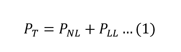
Total transformer loss PT (1) is the sum of no-load loss (excitation loss) PNL and load loss (impedance loss) PLL.
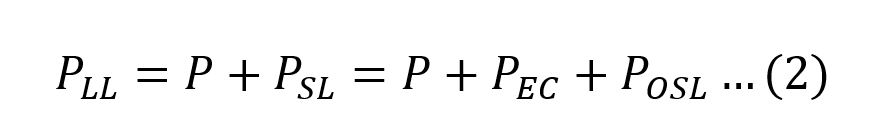
It is assumed in the proceeding work that the voltage harmonic distortion does not significantly increase the excitation loss, leaving the load loss the dominating source of loss at rated load. The load loss consists of copper loss, P (also referred to as I2R) and stray losses PSL. Stray loss is due to stray electromagnetic flux in the winding, core, core clamps, magnetic shields, enclosure, or tank walls [1]. The stray losses can be decomposed into eddy current losses in the winding PEC and other stray losses POSL (2).
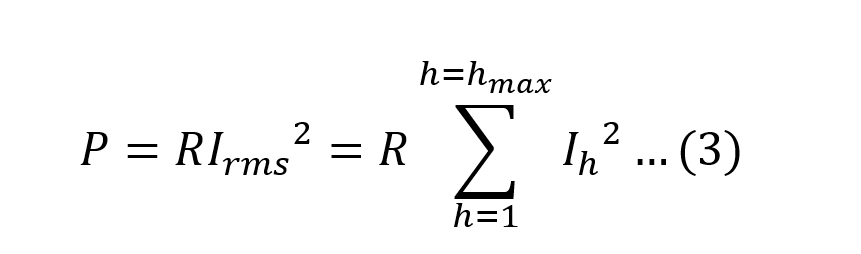
The copper loss is given by (3) and where the RMS current is decomposed into its harmonic content.
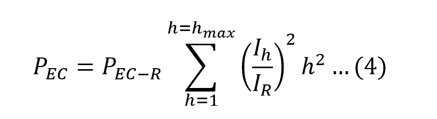
Winding eddy current loss in the power frequency spectrum is proportional to the square of both the load current magnitude and its frequency; and can cause excessive heating and abnormal temperature rise in the presence of non-sinusoidal load current.
It is found that other stray loss increases with the square of the current magnitude and by a harmonic exponent factor no greater than 0.8 [3].
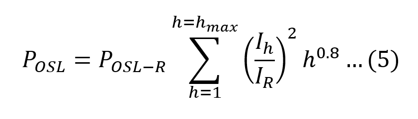
PEC-R and POSL-R are losses under rated conditions, and where IR and is the rated current.
K-Factor
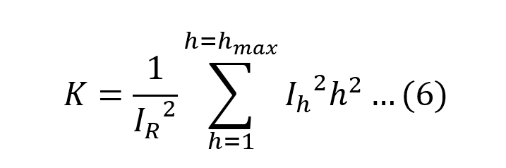
Underwriters Laboratories (UL) developed a metric called the K-factor [4], (6), a rating optionally applied to a dry-type transformer indicating its suitability for use with loads that draw non-sinusoidal currents and weights the harmonic currents according to their effect on transformer heating. The K-factor requires the rated current of the transformer.
The K-factor is used to specify a class of transformers capable of serving non-sinusoidal loads. K-factor rating of a transformer e.g. (4, 9, 13, 20, 30, 40 or 50) is an indication of the amount of harmonic current the transformer is capable of handling without overheating. The measured K-factor of the load must be below the K-factor rating of the transformer.
When comparing (4) and (6), the K-factor provides a measure of the ratio of the winding eddy current loss PEC to the eddy current loss under rated conditions PEC-R and therefore, a K-factor greater than unity indicates heating exceeding the rated operating conditions of the transformer. A standard transformer that is designed for linear loads is said to have a K-factor of unity.
Harmonic Loss Factor
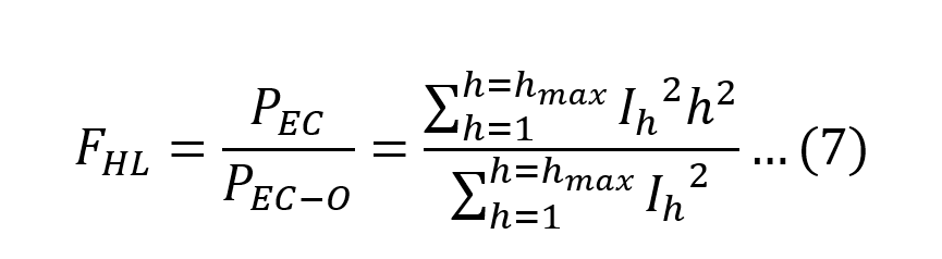
Harmonic loss factor FHL is defined in (7) as the ratio of the total winding eddy current losses due to the harmonics, PEC, to the winding eddy current losses at operating current and power frequency, as if no harmonic currents existed, PEC-O [1].
Similarly, the harmonic loss factor for other stray loss FHL-STR is calculated using (8) but not critical in estimating the derating in dry-type transformers [3].
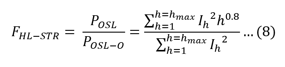
Note: is other stray losses at operating current and power frequency, as if no harmonic currents existed.
The K-factor and harmonic loss factor are related using (9).
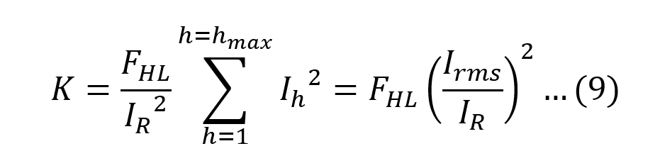
From (9), the K-factor and FHL are equal only when the RMS current value is equal to the rated current of the transformer. Under normal operating conditions the RMS current value should be less than the rated current and so the K-factor is less than FHL .
Derating
The maximum amount of harmonic load current that a standard transformer can deliver without exceeding rated operating conditions is given by (10) [5]. Imax (pu) is also used as a derating factor.
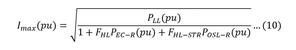
For dry-type transformers POSL-R (pu) is zero and (10) reduces to (11).
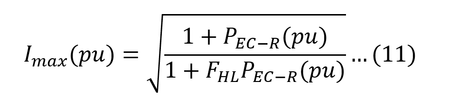
From (11) no derating is required when FHL is unity. Equation (11), rewritten in terms of K-factor will yield the same value of derating. The UL standard [4] prescribes another method for derating dry-type transformers using K-factor.
Factor K
Another method used to derate a standard oil-filled transformer to harmonic load is referred to as Factor K [6] and given in (12).
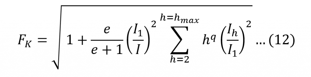
e is the eddy current loss due to sinusoidal current at the fundamental frequency, divided by the loss due to DC current equal to the RMS current of the sinusoidal current value, both at reference temperature. The exponent q is dependent on the type of windings and on the frequency. As a guide, q is set to 1.7 for transformers with round or rectangular wire in both low and high voltage windings and to 1.5 for transformers having low voltage foil windings. The derating factor is given by 1/FK.
Worked example
A VSD is connected to a transformer rated at 200A. The input current spectrum to the VSD resembles that of a six-pulse rectifier and normalised to 104.1A RMS. The rated eddy current loss PEC-R , e and q are set to 10%, 0.1 and 1.7 respectively. The transformer harmonic derating metrics are calculated using equations (6), (7), (8) and (12). Equations (11) and (12) are used to calculate the derating of dry-type and oil-filled type transformers respectively.
The maximum harmonic number is limited to 25 as provided in the IEEE Standard C57.110-1998 [3]. It is noteworthy that the skin effect becomes more pronounced with frequency and eddy-current loss is smaller than predicted; values are conservative in particular above the 19th harmonic [3].
In Figure 1 at each harmonic number, the harmonic derating metrics are calculated considering contributions of harmonics up to and including the harmonic number; and as expected the metrics increase in value with increasing harmonic number. The values at the 25th harmonic for FHL , K-factor, FHL-STR and Factor K are 8.35, 2.26, 1.34, and 1.15 respectively.
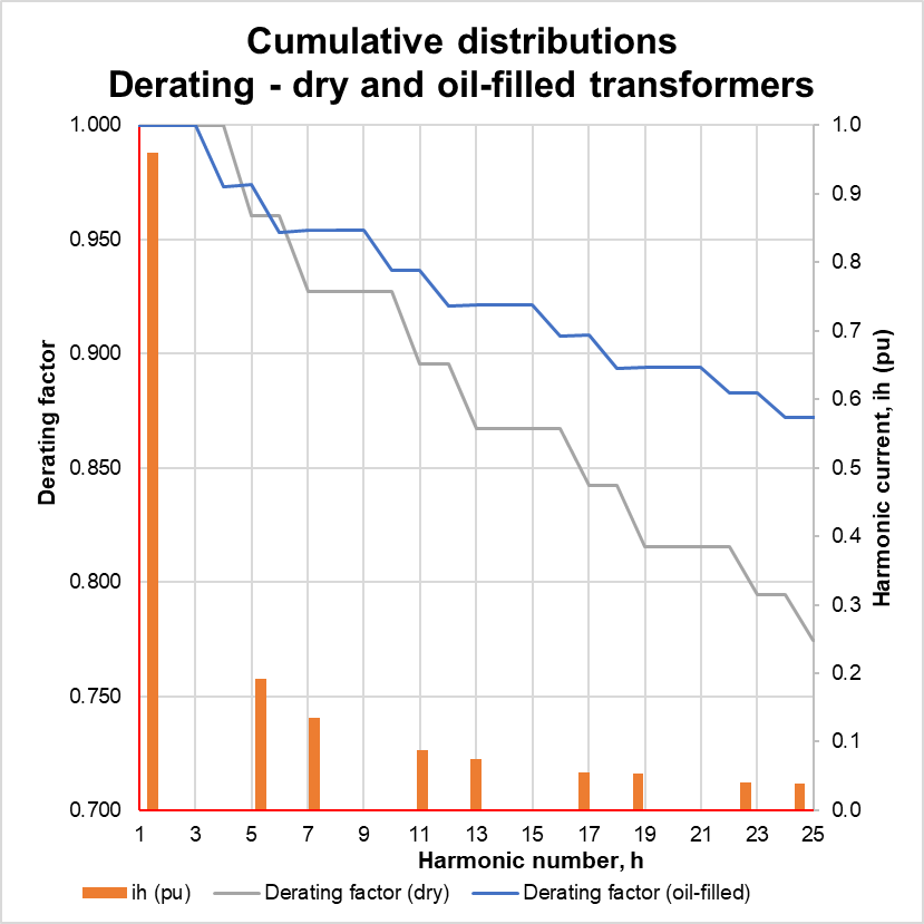
In Figure 2 the derating factors for dry-type and oil-filled type transformers are 77.4% and 87.2% respectively with equivalent operating currents of 155A and 174A.
Please contact CHK Power Quality for a free and no obligation demonstration or trial.
Phone: +61 2 8283 6945
Email: sales@chkpowerquality.com.au

References
[1] IEEE C57.110-1986, “IEEE Recommended Practice for Establishing Transformer Capability When Supplying Nonsinusoidal Load Currents”.
[2] M.A.S. Masoum, P.S. Moses, A.S. Masoum, “Derating of Asymmetric Three-Phase Transformers Serving Unbalanced Nonlinear Loads”, IEEE Transactions on Power Delivery, Vol. 23, No. 4, October 2008, pp. 2033-2041.
[3] IEEE C57.110-1998, “IEEE Recommended Practice for Establishing Transformer Capability When Supplying Nonsinusoidal Load Currents”.
[4] UL-1561-1994, “Dry-Type General Purpose and Power Transformers”.
[5] S.B. Sadati, A. Tahani, M. Jafari, M. Dargahi, “Derating of Transformers under non-sinusoidal Loads”, International Conference on Optimization of Electrical and Electronic Equipment, Brasov, Romania, pp. 263-268, 2008.
[6] EN50464-3: 2007, “Three-phase oil-immersed distribution transformers 50Hz, from 50kVA to 2500kVA with highest voltage for equipment not exceeding 36kV – Part 3: Determination of the power rating of a transformer loaded with non-sinusoidal currents”, April 2007.